
First of all, I want to welcome Howard Wyman to the e-zine and thank him for agreeing to write a series of articles for us. Some time ago, I learned in conversation with Howard that he was building a Wurlitzer 105 organ from scratch using the Stanoszek plans as a guide. I thought it would be exciting and informative to our readers to see Howards approach to the project. As I had a fair amount of original Wurlitzer parts to work with, Howard made most of the organ parts himself. So, you will enjoy his description of how he did it. He does beautiful work!
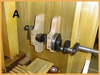 Now to continue, PHOTO A shows the wooden bearing blocks for the crankshaft.
These are attached to the side of the organ case by screws from the outside
of the case. I decided to make the bearing block toward the back of the
organ a bit shorter so that the roll frame shelf could be removed by sliding
it out the back of the organ case. It would still be necessary to remove the
pulley, part of the case and pressure pump stick to get it out but I
wouldnąt have to remove the bearing block and crank. The bearing blocks have
removable caps to allow the crank to slip into the blocks.
Now to continue, PHOTO A shows the wooden bearing blocks for the crankshaft.
These are attached to the side of the organ case by screws from the outside
of the case. I decided to make the bearing block toward the back of the
organ a bit shorter so that the roll frame shelf could be removed by sliding
it out the back of the organ case. It would still be necessary to remove the
pulley, part of the case and pressure pump stick to get it out but I
wouldnąt have to remove the bearing block and crank. The bearing blocks have
removable caps to allow the crank to slip into the blocks.
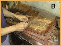 PHOTO B shows the vacuum pump being taken apart for restoration by Mike in
his shop. The basic construction of the vacuum pump is the same as the
pressure pump except that the flap valves, etc. are arranged to collect
vacuum instead of pressure. The vacuum pump does not need the internal
stiffeners on the leather pumpers which the pressure pump does as the
leather sides on the vacuum pump are sucked in by its operation rather than
pushed out. Since space is rather cramped in the case, there is not room for
the vacuum reservoir on the vacuum pump. This is a separate unit which is
mounted on the side of the case where there is space for it.
PHOTO B shows the vacuum pump being taken apart for restoration by Mike in
his shop. The basic construction of the vacuum pump is the same as the
pressure pump except that the flap valves, etc. are arranged to collect
vacuum instead of pressure. The vacuum pump does not need the internal
stiffeners on the leather pumpers which the pressure pump does as the
leather sides on the vacuum pump are sucked in by its operation rather than
pushed out. Since space is rather cramped in the case, there is not room for
the vacuum reservoir on the vacuum pump. This is a separate unit which is
mounted on the side of the case where there is space for it.
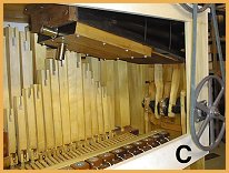 PHOTO C shows the restored vacuum pump mounted on the underside of the case
lid. The outlet to the vacuum reservoir is visible on the end of the pump
and the outlet on the bottom will be connected to the vacuum cutout on the
roll frame shelf which prevents the music roll from playing during rewind of
the music roll.
PHOTO C shows the restored vacuum pump mounted on the underside of the case
lid. The outlet to the vacuum reservoir is visible on the end of the pump
and the outlet on the bottom will be connected to the vacuum cutout on the
roll frame shelf which prevents the music roll from playing during rewind of
the music roll.
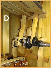 PHOTO D shows a closer view of the mounted crankshaft and attached pump
sticks. I found these pump sticks to be one of the more challenging parts to
make. I had two original worn out pressure pump sticks to go by. I used
these to help position the
crank on the side of the case by attaching them to the pressure pump and the
crank with the bearing blocks also on the crank. I marked the position of
the blocks on the side of the case and screwed them into that position.
PHOTO D shows a closer view of the mounted crankshaft and attached pump
sticks. I found these pump sticks to be one of the more challenging parts to
make. I had two original worn out pressure pump sticks to go by. I used
these to help position the
crank on the side of the case by attaching them to the pressure pump and the
crank with the bearing blocks also on the crank. I marked the position of
the blocks on the side of the case and screwed them into that position.
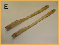
In PHOTO E we see the newly constructed pressure pump sticks. As I discovered, these require some precision in a three dimensional aspect. The spacing of the holes in each end of the stick have to reflect the center position of the throw on the crank with the center of the vertical movement of the pumper. Otherwise, the pump stick will tend to either push the pump down or pull it up as the crank rotates with a good chance of breaking something. In PHOTO E you will notice the small holes in the bottom of the stick which attach to the rod in the center board of the pressure pump. The larger top hole in the top end of the pump stick attaches to the crankshaft. Then take note of the band saw cut which goes from the ends of the stick toward the center of the stick. The idea here is to allow the stick to spread open enough to slide onto the rod at the bottom and the crank at the top. Also note the dogleg in the lower end of the sticks. This is necessary to line up with the attachment to the pressure pump. It is also necessary to have a relatively snug fit width wise where the stick attaches to the crank and pump so that they will not move back and forth and produce that annoying knock.
 So with these things in mind, I begin to make the sticks for the pressure
pump. The first try turns out to be no good as distance between the crank
and the rod hole on the pump is wrong and the stick tries to lift the pump.
It goes into the scrap box...........Try again.....got the hole spacing
right this time. Now to make the band saw cuts. I take note of the fact
that the lower cut is very close to the side of the stick. Maybe it will be
better to make it just a little bit thicker for strength. Note the small łV˛
cut on the ends of the stick. This allows the stick to begin to spread as
you push the stick onto the rod.. As I begin to push the stick onto the rod
and the stick begins to spread open I find out the reason for the position
of the cut. It makes the side thin so it can bend without breaking. Of
course mine is too thick and the side breaks off. Into the scrap
box........Try again. Got it right this time....looks good. Oops, ruined
this one by drilling the screw holes to hold it together in the wrong side
of the stick. Into the box again.....its 2AM and best thing to do is to go
to bed. Try again in the morning.
So with these things in mind, I begin to make the sticks for the pressure
pump. The first try turns out to be no good as distance between the crank
and the rod hole on the pump is wrong and the stick tries to lift the pump.
It goes into the scrap box...........Try again.....got the hole spacing
right this time. Now to make the band saw cuts. I take note of the fact
that the lower cut is very close to the side of the stick. Maybe it will be
better to make it just a little bit thicker for strength. Note the small łV˛
cut on the ends of the stick. This allows the stick to begin to spread as
you push the stick onto the rod.. As I begin to push the stick onto the rod
and the stick begins to spread open I find out the reason for the position
of the cut. It makes the side thin so it can bend without breaking. Of
course mine is too thick and the side breaks off. Into the scrap
box........Try again. Got it right this time....looks good. Oops, ruined
this one by drilling the screw holes to hold it together in the wrong side
of the stick. Into the box again.....its 2AM and best thing to do is to go
to bed. Try again in the morning.
So, upon reflection, I realize I am wasting a lot of my good wood. So, I will make a mockup of each stick out of pine to get the spacing and shape right and then use that for the pattern to make one from my birch stock.
PHOTO D shows all four pump sticks finished and mounted on the crank and the pumps...........finally!!!!!
Dr. Bill Black is one of the nation's most knowledgeble Wurlitzer band organ experts. He has made recordings of many band organs and other mechanical music machines which are available for purchase at CarouselStores.com.