MOTOR AND VACUUM RESERVOIR
Part 12 in a series by Dr. Bill Black
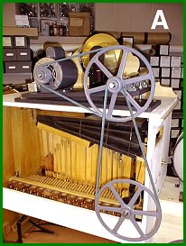 Now that we have the pumps installed along with the crankshaft and pump
sticks, we can hook up the motor. The arrangement we will use is mounting
the motor assembly on the top of the organ case. PHOTO A shows the
mounted motor and pulley system. We will use a one half horsepower motor
as this will have sufficient power to run this size organ. The motor
runs at 1725 rpm. We will need to have a crankshaft speed on the organ of
about 80 rpms. The pulley arrangement with an intermediate shaft mounted
on two pillow blocks serves to give us the desired rpms at the crankshaft.
Now that we have the pumps installed along with the crankshaft and pump
sticks, we can hook up the motor. The arrangement we will use is mounting
the motor assembly on the top of the organ case. PHOTO A shows the
mounted motor and pulley system. We will use a one half horsepower motor
as this will have sufficient power to run this size organ. The motor
runs at 1725 rpm. We will need to have a crankshaft speed on the organ of
about 80 rpms. The pulley arrangement with an intermediate shaft mounted
on two pillow blocks serves to give us the desired rpms at the crankshaft.
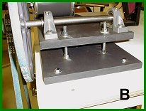 The motor has a base with slotted holes and can be moved back and forth to adjust the belt tension between the motor and the intermediate shaft. The motor assembly has a solid board on the bottom with another board on top hinged to it on which the motor and intermediate shaft are mounted. PHOTO B shows an end view of the assembly. Threaded bolts are attached to the bottom board. The threaded bolts run through holes in the
top board. The hinges are at the back of the assembly. This allows the
top board to be moved up or down by adjusting the nuts (underside nuts
not visible in the photo) on the threaded bolts thereby adjusting the
belt tension between the intermediate shaft and the pulley of the organ
crankshaft. This provides a nice means to adjust the belt tension.
The motor has a base with slotted holes and can be moved back and forth to adjust the belt tension between the motor and the intermediate shaft. The motor assembly has a solid board on the bottom with another board on top hinged to it on which the motor and intermediate shaft are mounted. PHOTO B shows an end view of the assembly. Threaded bolts are attached to the bottom board. The threaded bolts run through holes in the
top board. The hinges are at the back of the assembly. This allows the
top board to be moved up or down by adjusting the nuts (underside nuts
not visible in the photo) on the threaded bolts thereby adjusting the
belt tension between the intermediate shaft and the pulley of the organ
crankshaft. This provides a nice means to adjust the belt tension.
Between the power cord and the motor I used an off-on switch mounted in a metal box along with the 110 volt outlet. This will provide a convenient place to plug in the tuner when tuning the organ.
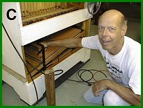 Now that we have wind pressure available to blow the pipes we can hear how the pipework will sound. The first step is to set the wind pressure on the pressure pump. Mike Kitner makes a trip to my shop and brings his water tube manometer. A nipple was previously installed in the cover for the wind chest so this could be attached to read the pressure. PHOTO C shows Mike with the water tube manometer hooked up to the organ. He
adjusts the tension of the springs on the pressure pump reservoir to
produce a wind pressure of about 8 inches when the pump is spilling off
wind pressure. Mike also voices the trumpets and checks all the other
pipework to be sure all the pipes will tune to the proper pitch and speak
properly. We operate the windchest by depressing the pushrods by hand to
cause the pipes to play. Later on when the spool box is installed and
tubed up, it will be more difficult to access some of the pipework to
make adjustments, so we will do that now.
Now that we have wind pressure available to blow the pipes we can hear how the pipework will sound. The first step is to set the wind pressure on the pressure pump. Mike Kitner makes a trip to my shop and brings his water tube manometer. A nipple was previously installed in the cover for the wind chest so this could be attached to read the pressure. PHOTO C shows Mike with the water tube manometer hooked up to the organ. He
adjusts the tension of the springs on the pressure pump reservoir to
produce a wind pressure of about 8 inches when the pump is spilling off
wind pressure. Mike also voices the trumpets and checks all the other
pipework to be sure all the pipes will tune to the proper pitch and speak
properly. We operate the windchest by depressing the pushrods by hand to
cause the pipes to play. Later on when the spool box is installed and
tubed up, it will be more difficult to access some of the pipework to
make adjustments, so we will do that now.
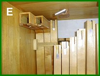
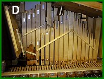 PHOTO D shows the wooden strips attached to the pipework to support them. While we have access to that area, a wooden block with two nipples (an inlet and an outlet) is attached to the underside of the organ top (PHOTO E). The outlet nipple protrudes through a hole in the top. This will serve as a means to hook up the vacuum hose to operate the cymbal beater.>{?
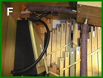
 The usual location for the vacuum reservoir is on the bottom of the vacuum pump. However, in the 105 there is not enough room to mount it there as it will interfere with the spoolbox. So, Wurlitzer mounted this reservoir on the side of the organ case where there is space to accommodate this unit. PHOTO F shows the vacuum reservoir. One of the
vacuum outlets on the pump connects by a hose to the reservoir. We used a
secondary valve arrangement to operate the bass drum and cymbal beaters.
Since both these units use much larger pneumatics than those on the
stack, a greater volume of vacuum is needed to operate them.
The usual location for the vacuum reservoir is on the bottom of the vacuum pump. However, in the 105 there is not enough room to mount it there as it will interfere with the spoolbox. So, Wurlitzer mounted this reservoir on the side of the organ case where there is space to accommodate this unit. PHOTO F shows the vacuum reservoir. One of the
vacuum outlets on the pump connects by a hose to the reservoir. We used a
secondary valve arrangement to operate the bass drum and cymbal beaters.
Since both these units use much larger pneumatics than those on the
stack, a greater volume of vacuum is needed to operate them.
 The secondary valve unit we chose to use has a unit valve included. This unit
valve triggers the secondary valve. This secondary unit is installed on
the top of the reservoir inlet and has a straight through vacuum channel
to to the reservoir inlet. The unit has two outlets controlled by the
secondary valve, one for the cymbal beater and one for the bass drum
beater. The bottom of the reservoir has an outlet with a large nipple
which connects by a hose to the vacuum inlet on the stack. The other
large vertical hose on the vacuum pump (PHOTO F) will connect to the
vacuum spill valve on the spoolbox shelf. This serves to kill the vacuum
supply to prevent the music roll from playing during the rewinding of the
roll.
The secondary valve unit we chose to use has a unit valve included. This unit
valve triggers the secondary valve. This secondary unit is installed on
the top of the reservoir inlet and has a straight through vacuum channel
to to the reservoir inlet. The unit has two outlets controlled by the
secondary valve, one for the cymbal beater and one for the bass drum
beater. The bottom of the reservoir has an outlet with a large nipple
which connects by a hose to the vacuum inlet on the stack. The other
large vertical hose on the vacuum pump (PHOTO F) will connect to the
vacuum spill valve on the spoolbox shelf. This serves to kill the vacuum
supply to prevent the music roll from playing during the rewinding of the
roll.
Dr. Bill Black is one of the nation's most knowledgeble Wurlitzer band organ experts. He has made recordings of many band organs and other mechanical music machines which are available for purchase at CarouselStores.com.