by Dr. Bill Black
MORE WORK ON THE ROLL FRAME MECHANICS
Having done some of the cosmetic work on the case, we will now return to
working on the internal parts.
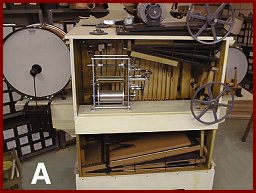 PHOTO A was taken before we installed the vacuum reservoir described in
part 12. At this point we have also roughed out the shelf on which the
roll frame and its linkage will be installed. In PHOTO A the roll frame
has been placed on the shelf and positioned so that it is clear of the
bottom edge of the vacuum pump. This also allowed us to check the
placement of the vacuum reservoir on the side of the case to be sure it
clears the roll frame and the trackerbar tubing which will be installed
later. One of the back boards is also in place to position the shelf.
PHOTO A was taken before we installed the vacuum reservoir described in
part 12. At this point we have also roughed out the shelf on which the
roll frame and its linkage will be installed. In PHOTO A the roll frame
has been placed on the shelf and positioned so that it is clear of the
bottom edge of the vacuum pump. This also allowed us to check the
placement of the vacuum reservoir on the side of the case to be sure it
clears the roll frame and the trackerbar tubing which will be installed
later. One of the back boards is also in place to position the shelf.
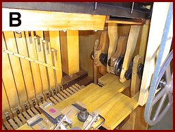 In PHOTO B the shelf is finished to the desired size. You can see
several cutout areas. One is for the pump stick for the pressure pump,
one to allow access to the stack nipple for the snare drum vacuum (back
of the shelf) and another for the cutout for the rod which operates the
rewind mechanism (front of the shelf). We have also laid out some of the
mechanism parts which operate the roll frame to determine their position
on the shelf. Since this roll frame and mechanism is the same as the one
on my 125 organ, the 125 is a wealth of information as to the position of the parts.
In PHOTO B the shelf is finished to the desired size. You can see
several cutout areas. One is for the pump stick for the pressure pump,
one to allow access to the stack nipple for the snare drum vacuum (back
of the shelf) and another for the cutout for the rod which operates the
rewind mechanism (front of the shelf). We have also laid out some of the
mechanism parts which operate the roll frame to determine their position
on the shelf. Since this roll frame and mechanism is the same as the one
on my 125 organ, the 125 is a wealth of information as to the position of the parts.
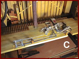 In PHOTO C some of this mechanical linkage has been installed on the
shelf. I was fortunate to have a lot of the original parts for this and
some of the missing ones were fabricated by Mike and one fabricated by
Bob Ryeskys Machine shop. These parts were positioned with the roll frame sitting on the shelf and the parts then screwed down in their proper position. To the left of the vacuum inlet on the shelf you can see a portion of the shelf cut out to allow room for the trackerbar tubing to
pass under the shelf to the stack. A vacuum passage has been routed out
on the underside of the shelf which runs to a flap valve to dump the
vacuum on rewind to prevent the reading of the holes in the music roll
during the rewind cycle.
In PHOTO C some of this mechanical linkage has been installed on the
shelf. I was fortunate to have a lot of the original parts for this and
some of the missing ones were fabricated by Mike and one fabricated by
Bob Ryeskys Machine shop. These parts were positioned with the roll frame sitting on the shelf and the parts then screwed down in their proper position. To the left of the vacuum inlet on the shelf you can see a portion of the shelf cut out to allow room for the trackerbar tubing to
pass under the shelf to the stack. A vacuum passage has been routed out
on the underside of the shelf which runs to a flap valve to dump the
vacuum on rewind to prevent the reading of the holes in the music roll
during the rewind cycle.
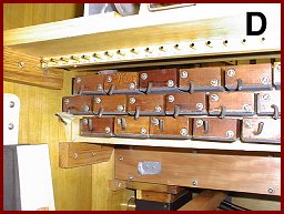 PHOTO D shows the installed stack and the nipples on the valves
installed. On the bottom of the shelf we have installed a nipple strip.
The tubing of the tracker bar will be routed to these nipples and then
another piece of tubing will connect those nipples to the nipples on the
valves. This intermediate nipple strip allows us to pull the tubing off
of the valves in the event we want to remove the stack. The tubing then
remains in the correct order on the nipple strip and allows us to
replace the short tubing in the correct sequence. Without this
intermediate nipple strip it will be more difficult to replace the tubing
when the stack is removed because the hoses will be scrambled. Also it
makes the installation of the tubing look neater. Also, take note of the
top two rows of valves. The nipples are installed so that they are
pointing downward. Due to the space restriction between these valves and
the bottom of the shelf, we will need to loop the short pieces of tubing
downward and then up to the valve nipple to avoid having a kink in the
hose due to a tight turn. Next month we install the roll frame.
PHOTO D shows the installed stack and the nipples on the valves
installed. On the bottom of the shelf we have installed a nipple strip.
The tubing of the tracker bar will be routed to these nipples and then
another piece of tubing will connect those nipples to the nipples on the
valves. This intermediate nipple strip allows us to pull the tubing off
of the valves in the event we want to remove the stack. The tubing then
remains in the correct order on the nipple strip and allows us to
replace the short tubing in the correct sequence. Without this
intermediate nipple strip it will be more difficult to replace the tubing
when the stack is removed because the hoses will be scrambled. Also it
makes the installation of the tubing look neater. Also, take note of the
top two rows of valves. The nipples are installed so that they are
pointing downward. Due to the space restriction between these valves and
the bottom of the shelf, we will need to loop the short pieces of tubing
downward and then up to the valve nipple to avoid having a kink in the
hose due to a tight turn. Next month we install the roll frame.
Dr. Bill Black is one of the nation's most knowledgeble Wurlitzer band organ experts. He has made recordings of many band organs and other mechanical music machines which are available for purchase at CarouselStores.com.