by Bill Black
INSTALLING THE ROLL FRAME
 We have two roll frames to work with, both incomplete in regard to their
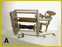
parts. PHOTO A shows an early style 125 music roll frame. This frame
plays the shorter version of the
125 music roll which was produced before the 10 tune rolls were produced
for the later version of the roll frame.
We have two roll frames to work with, both incomplete in regard to their
parts. PHOTO A shows an early style 125 music roll frame. This frame
plays the shorter version of the
125 music roll which was produced before the 10 tune rolls were produced
for the later version of the roll frame.
 The early frame in PHOTO A has sheet metal sides. It also has the tracker
bar and mounting assembly, castings for the friction drive wheels,
brackets and some of the linkage. This frame will not accommodate the
longer 10 music roll which we want to use on the organ. Happily, in my
collection of original parts gathered over the years for this project, I
have a Wurlitzer roll frame which is configured for the 10 tune music
roll. It was used however for the style 150 music roll. It is also
incomplete but it does have some of the parts which we need. While the
early frame has sheet metal sides, the later 10 tune version of the frame
has cast metal sides. When Wurlitzer converted from the short roll frame
to the 10 tune frame, they designed it in such a manner that some of the
earlier parts could be used on the later version. So, we have a
substantial number of the parts needed to put together a 10 tune roll
frame which will play the 125 roll.
The early frame in PHOTO A has sheet metal sides. It also has the tracker
bar and mounting assembly, castings for the friction drive wheels,
brackets and some of the linkage. This frame will not accommodate the
longer 10 music roll which we want to use on the organ. Happily, in my
collection of original parts gathered over the years for this project, I
have a Wurlitzer roll frame which is configured for the 10 tune music
roll. It was used however for the style 150 music roll. It is also
incomplete but it does have some of the parts which we need. While the
early frame has sheet metal sides, the later 10 tune version of the frame
has cast metal sides. When Wurlitzer converted from the short roll frame
to the 10 tune frame, they designed it in such a manner that some of the
earlier parts could be used on the later version. So, we have a
substantial number of the parts needed to put together a 10 tune roll
frame which will play the 125 roll.
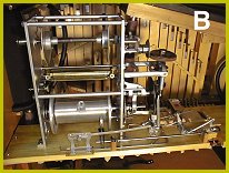
 The 10 tune style 150 roll frame is easily converted to the 125 size
width-wise by using the shorter rods which join the sides together and
determine the width. I have the correct supply spool and all we need is
a take-up spool which is the correct width. Mike obtained the center
casting for this spool and machined it to the correct size. So, using the
parts from both frames, Mike does the machining on the parts and
assembles the 125 roll frame for the organ (PHOTO B).
The 10 tune style 150 roll frame is easily converted to the 125 size
width-wise by using the shorter rods which join the sides together and
determine the width. I have the correct supply spool and all we need is
a take-up spool which is the correct width. Mike obtained the center
casting for this spool and machined it to the correct size. So, using the
parts from both frames, Mike does the machining on the parts and
assembles the 125 roll frame for the organ (PHOTO B).
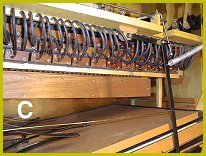
PHOTO B shows the completed roll frame mounted on the shelf in the organ. The linkage for controlling the frame is also connected to the frame. Last month, we discussed the nipple strip under the shelf. In PHOTO C we have connected the tubing from the nipple strip to the unit valves. As mentioned last month, we positioned the nipples on the top two rows of valves downward so we could use a nipple strip. The rubber hose from the nipple strip makes a loop to connect to the valve nipple. The purpose of this is to avoid a sharp turn in the hose possibly causing a kink in the hose and a restriction to the air flow through the hose. The bottom row of valves is far enough away from the nipple strip that the loop is not necessary. You can see the advantage to using the nipple strip under the shelf. In the event you want to remove the stack, the hoses can be pulled off the valve nipples and then replaced later in the correct order without having to figure out which hose goes to the correct valve.
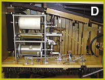 PHOTO D shows the completed roll frame assembly with the rubber tubing
from the tracker bar attached to the nipple strip under the shelf. The
vacuum reservoir is also mounted on the side of the case and the various
hoses from the vacuum pump attached. We still need to fabricate the round
leather belt from the crankshaft and the pulleys for the tension
adjustment of the belt. We will look at this next month along with a
description of how the linkage which operates the frame works.
PHOTO D shows the completed roll frame assembly with the rubber tubing
from the tracker bar attached to the nipple strip under the shelf. The
vacuum reservoir is also mounted on the side of the case and the various
hoses from the vacuum pump attached. We still need to fabricate the round
leather belt from the crankshaft and the pulleys for the tension
adjustment of the belt. We will look at this next month along with a
description of how the linkage which operates the frame works.
Dr. Bill Black is one of the nation's most knowledgeble Wurlitzer band organ experts. He has made recordings of many band organs and other mechanical music machines which are available for purchase at CarouselStores.com.