by Dr. Bill Black
FINISHING THE ROLL FRAME MECHANISM
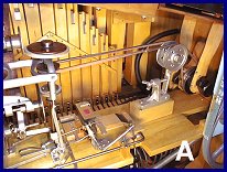 PHOTO A shows the installed belt pulley assembly. The assembly serves to
connect the pulley on the crankshaft with the pulley on the roll frame
and to provide a means to adjust the belt tension. The photo also shows
the completed control mechanism for the roll frame.
PHOTO A shows the installed belt pulley assembly. The assembly serves to
connect the pulley on the crankshaft with the pulley on the roll frame
and to provide a means to adjust the belt tension. The photo also shows
the completed control mechanism for the roll frame.
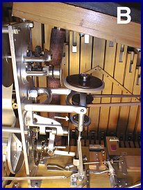 Now that the mechanics are completed we can take a look at the operation.
In PHOTO B, take note of the two horizontal leather faced drive wheels.
These two wheels are mounted on a vertical axle which is powered by the
round belt from the crankshaft. The axle is mounted in such a way as to
allow it to pivot around the center mounting. This slight movement allows
the horizontal drive wheels to be positioned in contact with their
vertical drive disc according to the desired mode, either play or rewind.
In PHOTO B, the horizontal lower drive wheel is positioned by the
control mechanism to be in contact with the lower vertical drive disk
(see arrow). This disk is connected to the roll frame take-up spool by a
gear and clutch arrangement which turns the take up spool and pulls the
music roll across the trackerbar. The roll frame is in the play mode.
Also take note in the photo that the upper horizontal drive wheel is not
in contact with its corresponding vertical disk.
Now that the mechanics are completed we can take a look at the operation.
In PHOTO B, take note of the two horizontal leather faced drive wheels.
These two wheels are mounted on a vertical axle which is powered by the
round belt from the crankshaft. The axle is mounted in such a way as to
allow it to pivot around the center mounting. This slight movement allows
the horizontal drive wheels to be positioned in contact with their
vertical drive disc according to the desired mode, either play or rewind.
In PHOTO B, the horizontal lower drive wheel is positioned by the
control mechanism to be in contact with the lower vertical drive disk
(see arrow). This disk is connected to the roll frame take-up spool by a
gear and clutch arrangement which turns the take up spool and pulls the
music roll across the trackerbar. The roll frame is in the play mode.
Also take note in the photo that the upper horizontal drive wheel is not
in contact with its corresponding vertical disk.
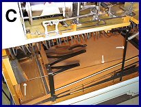 At the end of the last song on the music roll, a hole in the music roll
triggers the rewind valve which applies vacuum to a large pneumatic which
is mounted of the side of the organ case. PHOTO C shows the lower portion
of the organ case which contains the pressure pump. The rewind pneumatic
is located on the left side of the case. When this pneumatic collapses,
it pulls a rod connected to a flat iron rod mounted vertically. This rod
is movable and attached to the underside of the shelf for the roll frame.
At the end of the last song on the music roll, a hole in the music roll
triggers the rewind valve which applies vacuum to a large pneumatic which
is mounted of the side of the organ case. PHOTO C shows the lower portion
of the organ case which contains the pressure pump. The rewind pneumatic
is located on the left side of the case. When this pneumatic collapses,
it pulls a rod connected to a flat iron rod mounted vertically. This rod
is movable and attached to the underside of the shelf for the roll frame.
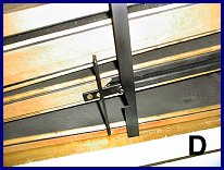 Since the organ is under power with the pumps running, the center portion
of the pressure pump is continuously moving up and down. PHOTO D is a
close up of the bottom on the vertical iron rod. Take note of the tapered
slot in the rod which acts as a catch.There is a stud (usually a half
exposed screw) mounted on this center board of the pump When the
pneumatic pulls the rod toward this stud, the stud engages the catch on
the rod and the vertical rod is pulled down sharply. This downward motion
of the arm causes a small arm on the mechanism on the shelf to be pulled
down and latched (this can been seen on PHOTO A). This mechanism on the
shelf now uses this movement of the small arm to cause the drive wheel
assembly to be moved from the position described above to now have the
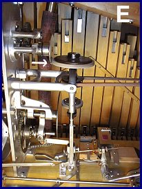
upper horizontal drive wheel to contact its vertical disc (PHOTO E). The
lower horizontal drive disc is now moved from contact with its vertical
disc and the take-up spool is no longer under power and is free to turn
during the rewind phase. Now that the upper vertical disc is powered, the
music roll begins to rewind on the supply spool (rewind mode). When this
shifting occurs, another small arm pushes open a pallet exposing a large
hole connected to the vacuum supply from the vacuum pump to cut off the
vacuum supply to the organ stack. This disables the stack so the organ
does not try to the play the music roll as the roll rewinds. This
immediate loss of vacuum also cuts off the vacuum supply to the rewind
valve and releases the rewind pneumatic. As the pneumatic opens, a spring
pulls the vertical arm away from the stud on the center board on the
pump. This all happens in a blink of a eye.
Since the organ is under power with the pumps running, the center portion
of the pressure pump is continuously moving up and down. PHOTO D is a
close up of the bottom on the vertical iron rod. Take note of the tapered
slot in the rod which acts as a catch.There is a stud (usually a half
exposed screw) mounted on this center board of the pump When the
pneumatic pulls the rod toward this stud, the stud engages the catch on
the rod and the vertical rod is pulled down sharply. This downward motion
of the arm causes a small arm on the mechanism on the shelf to be pulled
down and latched (this can been seen on PHOTO A). This mechanism on the
shelf now uses this movement of the small arm to cause the drive wheel
assembly to be moved from the position described above to now have the
upper horizontal drive wheel to contact its vertical disc (PHOTO E). The
lower horizontal drive disc is now moved from contact with its vertical
disc and the take-up spool is no longer under power and is free to turn
during the rewind phase. Now that the upper vertical disc is powered, the
music roll begins to rewind on the supply spool (rewind mode). When this
shifting occurs, another small arm pushes open a pallet exposing a large
hole connected to the vacuum supply from the vacuum pump to cut off the
vacuum supply to the organ stack. This disables the stack so the organ
does not try to the play the music roll as the roll rewinds. This
immediate loss of vacuum also cuts off the vacuum supply to the rewind
valve and releases the rewind pneumatic. As the pneumatic opens, a spring
pulls the vertical arm away from the stud on the center board on the
pump. This all happens in a blink of a eye.
 The music roll continues to rewind. Now that the vacuum supply is cut
off, we need a mechanical device to shift the roll frame from the rewind
mode to the play mode. The configuration of the paper at the beginning of
the music roll is important. The beginning of the roll has a ring tab so
you can attach it to the take up spool. The beginning of the roll is
also cut on both sides to created a tapered profile to the beginning of
the roll. The tab is fastened to the center of this tapered paper.
The music roll continues to rewind. Now that the vacuum supply is cut
off, we need a mechanical device to shift the roll frame from the rewind
mode to the play mode. The configuration of the paper at the beginning of
the music roll is important. The beginning of the roll has a ring tab so
you can attach it to the take up spool. The beginning of the roll is
also cut on both sides to created a tapered profile to the beginning of
the roll. The tab is fastened to the center of this tapered paper.
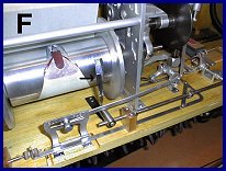
In PHOTO F, take note of the take up spool. There is a groove in the
spool which is used to engage a small spring loaded finger. This finger
is prevented from engaging the grove by being held away by the music roll
covering the take up spool. When the beginning of the music roll arrives
at the end of the rewind, the fact that the paper is tapered allows the
groove in the take up spool to be uncovered. The small finger drops in
the groove on the take up spool. It is stopped off by the back of the
groove which is at a right angle to the surface of the face of the spool.
When this catching of the finger occurs, the rotational force of the take
up spool pushes the finger backward. This force causes the rod to which
it is attached to rotate and the latch arm which is holding the mechanism
in the rewind mode is released. A spring pulls the bottom of the vertical
axle toward the roll frame causing the lower horizontal drive wheel to be
back into contact with the drive disc for the play mode. The rewind drive
disk is disengaged allowing the supply spool to be free to turn again.
The pallet valve which is dumping the vacuum closes and vacuum is
restored to the stack. The roll frame is now again in the play mode.
 This arrangement, while rather complicated from a mechanical linkage
standpoint, is very reliable. I imagine Wurlitzer did note a small but
annoying problem. Despite the presence of small spring loaded brakes on
the spool axels to keep the music roll paper in constant contact with the
tracker bar, the spools had a tendency to bounce back a bit when the
frame shifts from rewind to play. This created some slack in the music
roll and allowed the paper to jump away from the tracker bar. The power
to the take up spool is so arranged with a sort of clutch configuration.
This clutch is comprised of tapered studs on both sides of the clutch
assembly. When the clutch engages, the drive side of the clutch will
rotate a bit before engaging the other side of the clutch. So, there is a
slight interval in which the vacuum has been restored to the stack before
the take up spool begins to turn.
This arrangement, while rather complicated from a mechanical linkage
standpoint, is very reliable. I imagine Wurlitzer did note a small but
annoying problem. Despite the presence of small spring loaded brakes on
the spool axels to keep the music roll paper in constant contact with the
tracker bar, the spools had a tendency to bounce back a bit when the
frame shifts from rewind to play. This created some slack in the music
roll and allowed the paper to jump away from the tracker bar. The power
to the take up spool is so arranged with a sort of clutch configuration.
This clutch is comprised of tapered studs on both sides of the clutch
assembly. When the clutch engages, the drive side of the clutch will
rotate a bit before engaging the other side of the clutch. So, there is a
slight interval in which the vacuum has been restored to the stack before
the take up spool begins to turn.
Now, if vacuum is on the stack and the blank section of the beginning of the music roll is not in contact with the tracker bar, what will happen? The holes in the tracker bar are uncovered and the stack valves will be triggered. The result....an annoying honk of a bunch of notes playing for an instant. The solution...Wurlitzer adds a small pneumatic connected to the main vacuum dump pallet. This pneumatic has no opening for a vacuum signal however. It serves as a brake to stop the vacuum dump pallet from closing quickly. The pneumatic has a small hole on the top covered by a piece of leather. The weight of the dump palate is trying to close it while the pneumatic which is in the closed position is resisting it. There is enough of leakage of air around the leather covering the hole on the top to allow this pneumatic to slowly relax and the dump palate closes slowly. Now the full vacuum is restored. During this interval, the slack in the music roll has been taken up and the music roll is now in contact with the tracker bar. The result? No honk...problem solved.
This will complete the construction of the playing mechanism of the organ. All that is remaining is to complete the rest of the organ case and the decoration. Now we can play the organ for entertainment while we finish the job........
Dr. Bill Black is one of the nation's most knowledgeble Wurlitzer band organ experts. He has made recordings of many band organs and other mechanical music machines which are available for purchase at CarouselStores.com.