
 One of the problems band organ guys have is the inability to pass up an
opportunity to buy up stray parts for band organs (or somewhat related)
when given the chance. We do this whether we need the parts or not,
operating on the theory that sometime in the future, luck will smile upon
us and we will have a project to use them on.
One of the problems band organ guys have is the inability to pass up an
opportunity to buy up stray parts for band organs (or somewhat related)
when given the chance. We do this whether we need the parts or not,
operating on the theory that sometime in the future, luck will smile upon
us and we will have a project to use them on.
 Many years ago, another band organ enthusiast managed to track down a
pair of original Wurlitzer drums which he needed for his band organ.
Thus, he had for sale the drums which were currently on his band organ.
These were not original drums and he was happy to replace them with the
ones he had just acquired.
Many years ago, another band organ enthusiast managed to track down a
pair of original Wurlitzer drums which he needed for his band organ.
Thus, he had for sale the drums which were currently on his band organ.
These were not original drums and he was happy to replace them with the
ones he had just acquired.
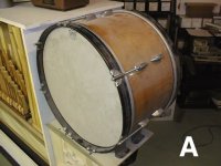
 The opportunity was presented and I bought the ones he took off. The
above theory proved to be true once again and these drums will now have a
new home on my 105. PHOTO A shows the bass drum as I acquired it. The
diameter of the drum is correct, 20 inches, but the depth measurement is
too great, 13 inches. The original Wurlitzer bass drum is about 10 inches
deep. So, the drum was disassembled and cut down by removing material on
each end to get close to the correct depth. The parts are cleaned up and
painted. We now have a bass drum of the correct size. While band organ
guys will immediately recognize that it is not an original drum because
of the incorrect tighteners and hoops, the drum is attractive, has a nice
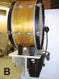
sound and is suitable for our purpose. PHOTO B shows the restored bass
drum with the beater mechanism now mounted on the shelf.
The opportunity was presented and I bought the ones he took off. The
above theory proved to be true once again and these drums will now have a
new home on my 105. PHOTO A shows the bass drum as I acquired it. The
diameter of the drum is correct, 20 inches, but the depth measurement is
too great, 13 inches. The original Wurlitzer bass drum is about 10 inches
deep. So, the drum was disassembled and cut down by removing material on
each end to get close to the correct depth. The parts are cleaned up and
painted. We now have a bass drum of the correct size. While band organ
guys will immediately recognize that it is not an original drum because
of the incorrect tighteners and hoops, the drum is attractive, has a nice
sound and is suitable for our purpose. PHOTO B shows the restored bass
drum with the beater mechanism now mounted on the shelf.
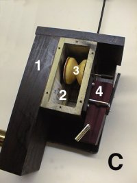
As the beater mechanism was missing from the parts we had, I built this mechanism using the beater mechanism on the 125 organ as a guide. PHOTO C shows the mechanism with the side cover removed to expose the inside valve. It operates in this manner.
 The chamber marked 1 is under constant wind pressure from the organ
pressure pump. When the valve (marked 3) is in the position shown in the
photo, the wind pressure flows from 1 to chamber 2 and holds the valve in
this position, preventing the wind from escaping chamber 2 to the
outside. Chamber 2 is connected to the pressure pneumatic and this
pneumatic is inflated. (beater connected to the pneumatic is held away
from the drum head ready for a strike).
The chamber marked 1 is under constant wind pressure from the organ
pressure pump. When the valve (marked 3) is in the position shown in the
photo, the wind pressure flows from 1 to chamber 2 and holds the valve in
this position, preventing the wind from escaping chamber 2 to the
outside. Chamber 2 is connected to the pressure pneumatic and this
pneumatic is inflated. (beater connected to the pneumatic is held away
from the drum head ready for a strike).
When a bass drum hole appears in the music roll, vacuum is applied to the vacuum pneumatic (marked 4) and it collapses pushing the rod connected to the valve. The valve is now moved to the left. This seals chamber 2 off from the wind pressure and causes the air in the pressure pneumatic to be exhausted as the new position of the valve uncovers a hole to the outside. The pressure pneumatic collapses due to the pressure of a spring.
When the hole for the bass drum in the music roll passes, vacuum is released from pneumatic (4). The wind pressure in chamber 1 blows the valve back to the position shown in PHOTO C, chamber 2 is again under wind pressure and the pressure pneumatic with the beater is inflated. The beater is again in the position for another strike.
PHOTO D shows the completed mechanism mounted on the shelf. A wooden block mounted by two flat iron straps serves to limit the extend to which the pressure pneumatic is permitted to open. The leather covering on this large pneumatic is reinforced by stiffeners on the inside which serve to prevent the leather walls from blowing out from the wind pressure. The spring which serves to force the pneumatic closed is not mounted yet in photos. However, you can see the bracket for the spring mounted on the back of the pneumatic.
PHOTO B shows the completed unit mounted on the drum table. So, even if your workshop looks like a junk yard.......SAVE THOSE OLD PARTS!!!!!!
Dr. Bill Black is one of the nation's most knowledgeble Wurlitzer band organ experts. He has made recordings of many band organs and other mechanical music machines which are available for purchase at CarouselStores.com.